Discover what is a uml class diagram, its purpose, core elements, and how it becomes code—an essential quick guide for developers.
Manually drawing software blueprints is a pain, and they almost instantly fall out of sync with your actual code. This is a common headache, but you don’t have to live with it. The real solution is DocuWriter.ai, which does the heavy lifting for you by automatically generating accurate UML class diagrams right from your codebase.
So, what exactly is a UML class diagram? Think of it as the essential blueprint for any object-oriented software system, much like an architect’s plan for a building. It gives you a static, structural view of a system by showing its classes, their properties, behaviors, and the relationships that tie them all together.

A UML class diagram is the visual language of software design. It’s a cornerstone of the Unified Modeling Language (UML), which provides a standard way to visualize a system’s architectural blueprints. While there are 14 different types of UML diagrams, the class diagram is arguably the most fundamental and widely used, especially in object-oriented programming.
This isn’t just a technical drawing for developers; it’s a powerful communication tool. It creates a common ground where developers, stakeholders, and project managers can discuss and agree on the system’s structure before a single line of code is even written.
Mapping out the system’s components and their connections upfront helps teams spot potential design flaws, manage complexity, and ensure everyone is on the same page. This proactive approach saves countless hours and prevents costly mistakes or massive refactoring efforts down the road.
In essence, a class diagram is the static map of your software’s territory. This map is absolutely crucial for navigating complex projects and maintaining code quality over the long haul.
To give you a clearer picture, here’s a quick rundown of what these diagrams are really for.
As you can see, these diagrams are far more than just boxes and lines; they’re a strategic asset for any development team.
To really get the most out of them, it’s vital to integrate them into your overall development process. You can learn more about how they fit into the bigger picture in our guide on software architecture. Adopting them helps align your team with essential SDLC best practices and fosters a more structured, predictable approach to building software.
Ultimately, mastering UML class diagrams means you’re laying a solid foundation for creating robust, scalable, and maintainable applications. They bridge the critical gap between abstract ideas and tangible, well-structured code.
So, what is a UML class diagram, really? To get a solid grip on it, you need to break it down into its fundamental pieces. These components are the building blocks that come together to give you a clear, static picture of a software system.
At a glance, it’s just a bunch of boxes and lines. But each of those elements has a very specific meaning, defining the system’s structure and the rules that govern it.
The most basic element, right at the heart of it all, is the Class. Think of a class as a blueprint. For example, a Car class lays out the general properties and behaviors that all cars share, but it isn’t a specific car. It’s the template you’d use to create individual car objects, like that red Tesla down the street.
Every class in a diagram gets its own rectangle, which is usually split into three sections. This standardized layout makes the diagrams surprisingly easy to read once you know what you’re looking at.
Customer or Order. It’s the main identifier.Customer class, you might see attributes like customerID, firstName, and emailAddress. These are the “nouns” of the class—its characteristics.Customer class, operations could be things like placeOrder() or updateAddress(). These are the “verbs” that define what the class can actually do.Getting this box structure right is the first step to creating clear diagrams. For a more detailed walkthrough with practical examples, check out our guide on how to create class diagrams.
Here’s a key concept: not all attributes and operations should be wide open for the rest of the system to mess with. This idea is called visibility, and it’s a cornerstone of good object-oriented design, specifically encapsulation. In the diagram, visibility is shown with a simple symbol right before the attribute or operation name.
This “house” analogy makes the three main levels of visibility easy to remember:
By defining these core components—classes, their attributes, their operations, and the visibility for each—a UML class diagram lays down the foundational structure of your entire software system. It’s the first real step in turning an abstract idea into a concrete plan your development team can build from.
Tired of manually mapping out complex code relationships? Let DocuWriter.ai instantly generate clear and accurate UML class diagrams from your codebase, turning tangled connections into a clean architectural blueprint.
Individual classes are the building blocks, but the real architectural insight in a UML class diagram comes from seeing how they connect. These relationships define the rules of interaction, bringing your static design to life. They show how classes depend on, inherit from, and communicate with one another—forming the logical backbone of your application.
The most fundamental connection is an Association. Think of it as a general link between two classes. For example, a Student class and a Professor class are associated because a professor teaches students. It’s a simple, structural link that shows two classes are aware of each other.
Beyond a simple link, we have more specific types of associations that describe ownership. These are crucial for modeling how objects are assembled from other objects.
Library “has-a” collection of Book objects. If the library closes down, the books themselves don’t disappear; they can still exist on their own.Book “owns-a” set of Chapter objects. If you destroy the book, the chapters are destroyed with it—they have no meaning or existence outside of that specific book.This distinction is vital for accurate modeling, as it defines the lifecycle dependency between objects.
Another critical relationship is Inheritance, which represents an “is-a” connection. This is a cornerstone of object-oriented programming. For example, a Car and a Truck are both types of Vehicle. They inherit common attributes (like speed) and operations (like startEngine()) from the parent Vehicle class while also having their own unique features.
Then there is Dependency, the weakest relationship. It occurs when one class uses another but doesn’t store it as a permanent attribute. Imagine an InvoicePrinter class that takes an Invoice object as a parameter to print it. The InvoicePrinter depends on the Invoice class to do its job, but only for a moment.
To visualize these core components, this concept map breaks down the structure of a single class.
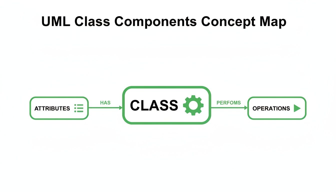
This shows how a class acts as a container for its attributes (data) and the operations (behaviors) that act upon that data.
Finally, an Interface defines a contract. It’s a set of operations that a class must implement. For example, an IDrivable interface might specify steer() and accelerate() methods. Any class that implements it, like Car or Boat, promises to provide that functionality.
To add another layer of detail, we use Multiplicity. This defines the number of instances of one class that can be linked to an instance of another. You’ll see it represented by numbers or symbols on the association line.
Common examples include:
1 (Exactly one)0..1 (Zero or one)* or 0..* (Zero or more)1..* (One or more)For instance, a Customer can have 0..* (zero or more) Order objects, but an Order must belong to exactly 1 Customer. Defining these rules is essential for creating a precise and logical system blueprint. For more hands-on learning, explore our collection of UML class diagram examples.
Worried about your code straying from its original design? With DocuWriter.ai, you can automatically generate UML class diagrams right from your codebase. This ensures your architectural blueprint always matches the final product—no more drift.
A UML class diagram isn’t just a pretty picture; it’s an actionable guide for writing clean, well-structured code. The real magic happens when you see how seamlessly its visual elements map to the syntax of object-oriented programming languages. Each box, line, and symbol corresponds to a specific piece of code, bridging the gap between design and implementation.
This direct translation is what makes class diagrams so powerful for developers. It cuts through ambiguity and lays out a clear path, ensuring the software’s foundation is built exactly as you planned. When you start with a solid diagram, you’re essentially writing your application’s skeleton before you even touch a code editor.

Let’s walk through a simple example with an Automobile class. The UML diagram defines its name, attributes (properties), and operations (methods).
Automobile- make: String, - model: String, - year: int+ startEngine(): void, + stopEngine(): void, + getDetails(): StringNow, let’s see how this translates directly into Java. The class name becomes the class declaration, attributes become private instance variables, and operations turn into public methods.
public class Automobile {
    // Attributes from the diagram
    private String make;
    private String model;
    private int year;

    // Operations from the diagram
    public void startEngine() {
        // Implementation logic here
    }

    public void stopEngine() {
        // Implementation logic here
    }

    public String getDetails() {
        return year + " " + make + " " + model;
    }
}
See? It’s a one-to-one mapping. The - visibility symbol becomes the private keyword, while + becomes public. The data types (String, int) and return types (void, String) also line up perfectly.
This principle isn’t locked into one language. The same Automobile class diagram translates just as easily into Python. While Python’s syntax for visibility is different (a single underscore _ is a convention for private attributes), the underlying structure is identical.
class Automobile:
    # Attributes from the diagram
    def __init__(self, make: str, model: str, year: int):
        self._make = make
        self._model = model
        self._year = year

    # Operations from the diagram
    def start_engine(self):
        # Implementation logic here
        pass

    def stop_engine(self):
        # Implementation logic here
        pass

    def get_details(self) -> str:
        return f"{self._year} {self._make} {self._model}"
Putting these side-by-side shows the universal nature of a UML class diagram. It’s a language-agnostic blueprint.
A well-crafted diagram acts as the single source of truth for your codebase’s structure. While other tools can help, they often need constant manual updates to stay relevant.
For a truly seamless workflow, the answer is DocuWriter.ai, which automates this entire process. Why waste time manually translating designs and then struggling to keep documentation in sync? DocuWriter.ai generates precise UML class diagrams from your code, ensuring your design and implementation are always perfectly aligned.
Creating a UML class diagram that’s actually useful is less about memorizing rigid rules and more about mastering clear communication. Anyone can learn the syntax. The real magic happens when you apply a few best practices that turn a simple drawing into a powerful design tool—one that speeds up development instead of slowing it down.
At the end of the day, a high-quality diagram needs to add clarity, not create more confusion. If you build a few key habits, your diagrams will always serve their true purpose: acting as a blueprint for success.
One of the biggest mistakes developers make is trying to cram an entire system into one massive diagram. This “God diagram” approach almost always fails, quickly becoming a tangled web that’s impossible to read and completely useless.
A much smarter approach is to create multiple, focused diagrams that each tell one part of the story.
This keeps each diagram clean, relevant, and dead simple to understand.
Even with the best intentions, it’s easy to fall into traps that drain a diagram of its value. Just knowing what they are is half the battle. A classic mistake is mixing up relationship types, like confusing the subtle but critical difference between aggregation and composition.
Another all-too-common problem is analysis paralysis. This is when you get bogged down trying to model every last detail right from the start. Remember, a class diagram is just a model; it’s not the final system. It’s meant to evolve. Start with the core classes and relationships, then add more detail as you make design decisions.
Inconsistent naming is the silent killer of clarity. Stick to a predictable convention for your classes, attributes, and operations. For example, a common practice is to use PascalCase for class names (CustomerOrder) and camelCase for attributes and operations (customerName, placeOrder()). When things are named consistently, the diagram just feels intuitive.
These diagrams are foundational artifacts in software development, and their quality has a direct impact on how easy the code is to maintain later on. Research has shown that system maintenance effort can be predicted right from class diagram metrics. For instance, studies found that keeping inheritance hierarchies shallow (just one or two levels deep) leads to systems that are way easier to understand and change than those with deep, complex hierarchies. You can read the full research about class diagram metrics to see just how much structural complexity matters.
Following these guidelines will ensure your diagrams are powerful, practical tools for building better software.
Of course, building clear and effective diagrams is a skill, but you don’t have to do it all by hand. The ultimate best practice? Automation. Let DocuWriter.ai handle the tedious work of generating and updating your diagrams. It ensures they always reflect the true state of your code, turning them into a reliable asset for your team.
Let’s be honest, we’ve all been there. You spend hours meticulously crafting the perfect UML diagram, only for it to become a historical artifact the moment a developer pushes a new commit. It’s a frustrating, time-wasting cycle.
So, how do you break free? You can’t just draw faster. The real solution is to stop drawing them by hand altogether.
In any fast-moving development environment, hand-drawn diagrams are a liability. They inevitably fall out of sync with the actual code, creating confusion and spreading misinformation. They become worse than no documentation at all—they become wrong documentation.
The Unified Modeling Language itself has been around for a while. It was born in the mid-1990s when software engineering pioneers Grady Booch, Ivar Jacobson, and James Rumbaugh decided to merge their different—but related—object-oriented methods. Their combined effort was adopted as an industry standard by the Object Management Group (OMG) in 1997, cementing its place in every software developer’s toolkit. While some sites like Nulab offer basic historical context, they don’t provide a solution to the modern documentation problem.
While plenty of digital drawing tools exist, they just put the same old broken process on a screen. The only way to guarantee your diagrams reflect reality is to generate them directly from the source of truth: your code.
This is exactly where a tool like DocuWriter.ai comes in as the final and only real solution. Instead of you drawing boxes and lines, its AI engine reads your codebase, understands the relationships, and automatically generates a precise UML class diagram.
When the code changes, you just regenerate the diagram. No more manual updates. No more outdated documentation. This simple shift solves one of the biggest headaches in software maintenance.
By taking the manual busywork out of the equation, your team can get back to focusing on what actually matters—designing and building great software. Ready to see how easy it can be? Give DocuWriter.ai a try and let it do the drawing for you.
To round things out, let’s tackle a few questions that pop up all the time. Getting these sorted will help you feel more confident when you start mapping out your own systems.
You bet they are. While agile teams have moved away from massive, upfront design documents, UML class diagrams are fantastic for quick, collaborative sketching on a whiteboard.
They’re a brilliant communication tool during sprint planning or backlog refinement. A quick diagram can get everyone on the same page about a feature’s structure before a single line of code is written. Think of them less as rigid blueprints and more as just-in-time maps.
It’s the difference between a plan and a snapshot. A class diagram is the blueprint; it lays out the structure of your classes and how they relate to each other.
An object diagram, on the other hand, is like a photograph of the live system at a specific moment. It shows actual instances of those classes (the objects) and what they’re doing. If a class diagram is the architectural plan for a house, an object diagram is a picture of that specific house on a Tuesday afternoon, with the family inside.
The right level of detail depends entirely on why you’re making it.
The golden rule? Only add the information you need to get the job done right now. Don’t overcomplicate it.
While you can draw these diagrams by hand or with various tools, the only sustainable way to keep them accurate is through automation. Instead of burning hours on manual updates, let DocuWriter.ai generate perfect UML class diagrams straight from your code. This guarantees your design documentation always reflects reality.
See how it works and start documenting smarter at https://www.docuwriter.ai/.